UART TX
This short Verilog project is intended for basic communications or as a debug tool for other larger projects. It implements a UART transmitter at a selectable baud rate, with the common “8N1” (8 data bits, no parity, 1 stop bit) format.

I developed this on a Terasic DE10-Lite board, which has an Altera MAX10 FPGA, using the Quartus Prime 20.1, Light Edition toolchain. Outside of the I/O mapping, nothing is really specific to this particular board or FPGA part, and the code can be easily adapted to other hardware.
For Verilog beginners, the project has examples of simple finite state machines, case statements, concatenation, a synchronizer or two, localparams, module instantiation “by name”, and a synthesizable test module.
UART Basics
Ample discussions of UART communications can be found on allaboutcircuits.com, Sparkfun, and Wikipedia, but I’l also point out a few highlights below.
For the details on my implementation, the code is well commented so please check it out. The full Quartus project is up on my GitHub site and the two relevant Verilog source files are also included at the bottom of this page.

Typical UART data framing
A few few interesting UART nuances to remember:
- the serial output line (TX) idles HIGH. For a logic-level UART interface (i.e. not RS-232 voltage levels) that means at 3.3V, or 5V, etc based on the I/O line supply voltage
- there must be a START bit. This ensures that the receiver can detect when data is coming, and synchronize it’s sampling of the upcoming bits
- the data item can be smaller than 8 bits, but 8 is by far the most common size, and what is implemented in this design
- a PARITY bit is optional, and not implemented here
- one STOP bit is used here. This means that the complete transmission lasts 10 bit durations: start bit + 8 data bits + stop bit = 10 bits
- Most systems transmit the data byte in reverse order, i.e. LSBit first, MSBit last, which is done in this implementation
Test Wrapper (not a Test Bench, per se)
I didn’t create a test bench for simulation, but instead created test code that is synthesizable and can be run on the board to demo the UART transmitter. The tester code (uart_tx_tester.v) feeds the UART transmitter module (uart_tx.v) with a 16 byte message every few seconds, and monitors the busy signal to correctly pace the data.
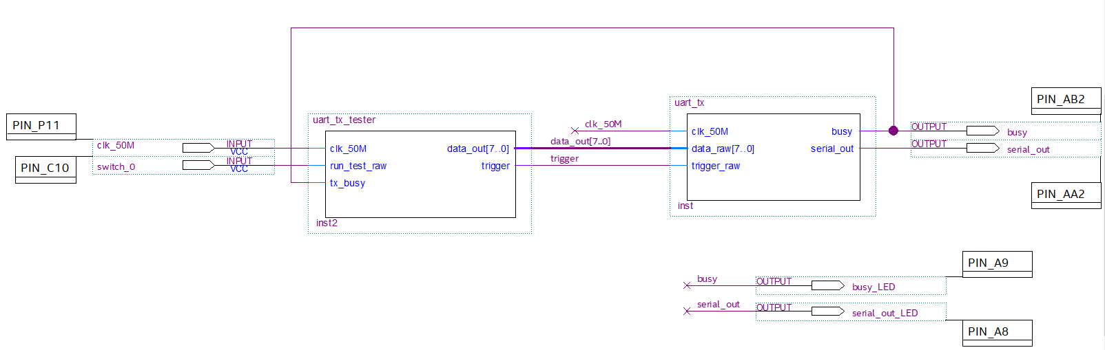
I chose to use a Quartus schematic file for the top level entity since it clearly shows the how the I/O and Verilog modules are connected. This could have been done programmatically with Verilog as well, but I figured this was clearer to follow.
I/O Interface
The interface to the UART transmitter module (uart_tx.v) is small:
Inputs:
- single byte for the character to transmit
- trigger flag to initiate transmitting
Outputs:
- serial data, i.e. the transmit (or TX) line that streams out the data
- busy flag for handshaking with the module that is providing the bytes to transmit. This indicates when the transmitter is still shifting out bits for the current byte, and can be used to check if the transmitter is ready for a new byte
Note:
This implementation does not have any FIFO‘s or buffers, so the module providing the data needs to pay attention to the busy flag to avoid overruns.
The full Quartus project including all source files is on my GitHub. The two more interesting Verilog source files are also included below.
Hello World… anyone listening?

Quick test at 57.6Kbaud
uart_tx_tester.v – synthesizable test code wrapper
//  ------------------------------------------------------------------------------
//
//  uart_tx_tester.v -- synthesizable tester for uart_tx.v
//
//  Copyright (C) 2020 Michael Gansler
//
//  This program is free software: you can redistribute it and/or modify
//  it under the terms of the GNU General Public License as published by
//  the Free Software Foundation, either version 3 of the License, or
//  (at your option) any later version.
//
//  This program is distributed in the hope that it will be useful,
//  but WITHOUT ANY WARRANTY; without even the implied warranty of
//  MERCHANTABILITY or FITNESS FOR A PARTICULAR PURPOSE.  See the
//  GNU General Public License for more details.
//
//  You should have received a copy of the GNU General Public License
//  along with this program.  If not, see <https://www.gnu.org/licenses/>.
//
//  ------------------------------------------------------------------------------
//
//  Module:       uart_tx_tester.v
//
//  Objective:    Synthesaizable tester for uart_tx by feeding it a 16 byte
//                message every few seconds for testing on hardware
//                with a scope or logic analyzer.
//
//  Assumptions:  50 MHz input clock
//                16 byte long test message
//                Development done on Terasic DE10-Lite board with Altera MAX10 FPGA
//
//  Notes:        This is a simple tester module to test uart_tx.v.  This is
//                synthesizable code which sends a 16 byte ASCII message to
//                uart_tx every few seconds. It drives the data and trigger
//                lines while monitoring the busy line to pace the characters.
//
//                A full test bench for simulation would also be helpful, but has
//                not yet been created at this time.
//
//
`default_nettype none                // Require all nets to be declared before used.
                                     // --> typo'd net names get trapped


module uart_tx_tester
(
   input                clk_50M,          // Input clock, assumed 50 MHz
   input                run_test_raw,     // HIGH indicates to continuously run test
   input                tx_busy,          // HIGH indicates transmitter is busy

   output  reg   [7:0]  data_out,         // Data byte (8 bits) to transmit
   output  reg          trigger           // Trigger to tell UART module to begin transmission
);

reg                     run_test_0   = 0;           // Synchronizer for 'start test' switch input
reg                     run_test     = 0;           // Synchronizer for 'start test' switch input

reg         [5:0]       tester_state = 0;           // FSM state variable

reg        [31:0]       byte_index   = (8*16)-1;    // Pointer to beginning of next byte to transmit in 16 byte message

reg        [31:0]       pause_delay  = 0;           // Counter for delay between re-transmissions of message

reg         [5:0]       trigger_ctr  = 0;           // Delay to hold trigger high, in clock cycles

                                 // Byte position:
                                 //
                                 // 111111
                                 // 5432109876543210
reg  [(8*16)-1:0]       byte_str = "Hello World!    ";  // 16 byte message to transmit

localparam STATE_IDLE       = 6'b00_0000;           // Legal values for tester_state
localparam STATE_LOAD       = 6'b00_0010;           // Legal values for tester_state
localparam STATE_TRIGGER    = 6'b00_0100;           // Legal values for tester_state
localparam STATE_POLL_BUSY  = 6'b00_1000;           // Legal values for tester_state
localparam STATE_PAUSE      = 6'b01_0000;           // Legal values for tester_state

localparam MSG_DELAY        = 32'd100_000_000;      // Delay between messages re-transmissions, in clk cycles

//
// Synchronizer for "run_test" input since, as tested, this comes from a
// slide switch on the DE10-Lite board, which is not synchronous with the
// clock.  See more on clock domain crossing and metastability to better
// understand this topic.
//
always @(posedge  clk_50M) begin

   run_test_0 <= run_test_raw;
   run_test   <= run_test_0;

end

//
// Main Finite State Machine that sequences the test
//
always @(posedge  clk_50M) begin

   case (tester_state)

      //
      // Wait for request to begin test.
      //
      STATE_IDLE: begin

         trigger <= 1'b0;

         if (run_test) begin

            byte_index   <= (8*16)-1;      // Point to 1st bit of 1st byte in message.
            tester_state <= STATE_LOAD;    // Move on to next state.

         end

      end

      //
      // Output next byte to transmitter module, with trigger still low
      // so it won't transmit yet.
      //
      STATE_LOAD: begin

         trigger      <= 1'b0;                       // Make sure trigger is LOW while setting data byte.
         data_out     <= byte_str[byte_index -:8];   // Set data byte to transmit.
         trigger_ctr  <= 6'd5;                       // Init counter which defines trigger HIGH time.
         tester_state <= STATE_TRIGGER;              // Move on to next state.

      end

      //
      // Now that previous state output'd the next byte to transmit,
      // assert the trigger signal to begin the transmission.
      //
      STATE_TRIGGER: begin

         trigger     <= 1'b1;                  // Assert trigger to begin transmission.
         trigger_ctr <= trigger_ctr - 6'd1;    // Keep trigger high for N cycles to accommodate synchronizer
                                               //  in uart_tx module.  Handles latency between trigger assertion
                                               //  here and FSM in uart_tx module beginning transmission and
                                               //  setting the busy flag.

         if (trigger_ctr==0)
            tester_state <= STATE_POLL_BUSY;   // Move on to next state.

      end

      //
      // Clear trigger signal, and wait until all bits shifted out
      // for the current byte.
      //
      STATE_POLL_BUSY: begin

         trigger <= 1'b0;                       // Clear trigger flag now that N cycles have passed.

         if (~tx_busy) begin                    // Check to see if uart_tx module still shifting out bits.

            if (byte_index<=7) begin            // Check to see if just transmitted last byte of message.  7 since that
                                                // is the location of the MSbit of the final byte of the message.
               pause_delay  <= 32'd0;           // All done transmitting message, so setup for delay between message transmissions.
               tester_state <= STATE_PAUSE;     // Move on to next state.

            end else begin

               byte_index   <= byte_index - 32'd8;  // More bytes to send so point to next byte.
               tester_state <= STATE_LOAD;          // Move on to next state.

            end

         end

      end

      //
      // Once transmitted full message, pause before
      // transmitting message again for testing convenience.
      //
      STATE_PAUSE: begin

         pause_delay <= pause_delay + 32'd1;

         if (pause_delay>MSG_DELAY)            // Wait for delay to expire.
            tester_state <= STATE_IDLE;

      end

      //
      // Should never get here, but if do, return to IDLE
      //
      default : begin

         tester_state <= STATE_IDLE;

      end

   endcase

end

endmodule
uart_tx.v – UART transmitter module
//  ------------------------------------------------------------------------------
//
//  uart_tx.v -- implements a UART transmitter
//
//  Copyright (C) 2020 Michael Gansler
//
//  This program is free software: you can redistribute it and/or modify
//  it under the terms of the GNU General Public License as published by
//  the Free Software Foundation, either version 3 of the License, or
//  (at your option) any later version.
//
//  This program is distributed in the hope that it will be useful,
//  but WITHOUT ANY WARRANTY; without even the implied warranty of
//  MERCHANTABILITY or FITNESS FOR A PARTICULAR PURPOSE.  See the
//  GNU General Public License for more details.
//
//  You should have received a copy of the GNU General Public License
//  along with this program.  If not, see <https://www.gnu.org/licenses/>.
//
//  ------------------------------------------------------------------------------
//
//  Module:       uart_tx.v
//
//  Objective:    Acts as a UART transmitter, converting 8 bit parallel data to
//                serial, at user-selected baud rate.
//
//  Assumptions:  - Data format is 8N1
//                - 50 MHz input clock
//                - No clock domain crossings accomodated for, though a synchronizer
//                  is included on the trigger input.  ** See comments below. **
//                - Development done on Terasic DE10-Lite board with Altera MAX10 FPGA
//
//                NOTE!!! -- If this module were used in an actual situation
//                with clock domain crossings or asynchronous inputs,
//                more attention (i.e. code changes) would be necessary to manage
//                the situation.
//
//  Notes:        Transmits 8 bits of data, plus start and stop bit, with no
//                parity bit, at the selected baud rate.  This is, often
//                refered to as "8N1" - 8 data bits, no parity, 1 stop bit.
//
//                Baud rate is selectable via a localparam.  Explanation of
//                the calculation and values for a number of common baud rates
//                are found in the comments elsewhere in this file.  Other
//                baud rates can of course be used, but have not been tested.
//
//                The trigger signal begins a transmission.  The data byte is also
//                latched at the trigger event to ensure that if the parent module
//                modifies the data byte during the transmission, it
//                has no averse effect on the transmission already in progress.
//
//                NOTE!!! -- There is a synchronizer included on the
//                trigger input.  If this module is being used with an
//                asynchronous trigger input or certain types of clock domain
//                crossings, this can help with avoiding metastability.
//
//                NOTE!!! -- If this module were used in an actual situation with
//                clock domain crossings or asynchronous inputs,
//                more attention (i.e. code changes) would be necessary to
//                manage the situation.
//
//                This synchronizer creates latency between assertion of the
//                trigger_raw input and actual initiation of the transmission.
//                Monitoring the "busy" signal during this latency must be
//                done with care since monitoring too early could appear
//                that the transmission is complete (i.e. not busy) even though
//                it has not begun yet due to the synchronizer latency.
//                See the tester module "uart_tx_tester.v" for an example
//                of how this is managed using a short stretched HIGH time
//                for the trigger signal before polling the busy signal.
//
//                The busy signal indicates when a transmission is in progress.
//                This is useful to throttle the parent module that is
//                sending data to this module, since UART serial
//                rates are typically slow by present day standards.
//
//                Post transmission an additional delay is performed in
//                the "cleanup" state.  Not absolutely necessary, but makes
//                it easier to interpret on a logic analyzer or oscilloscope.
//                This comes at the expense of a slower back to back byte
//                repetition rate.  Many recipients probably can't handle
//                immediate back to back bytes, so not really a huge limitation.
//                This area could be reworked if more performance is necessary.
//
//
`default_nettype none                  // Require all nets to be declared before used.
                                       // --> typo'd net names get trapped

module uart_tx
(
   input              clk_50M,         // Input clock, assumed 50 MHz
   input     [7:0]    data_raw,        // Data byte (8 bits) to transmit
   input              trigger_raw,     // Tells module to begin transmission of data_raw byte

   output reg         busy,            // Flag to indicate a transmission is in progress
   output reg         serial_out       // UART output serial datastream
);


reg          [3:0]    tx_state  = 0;   // State variable for main finite state machine

reg          [9:0]    data_aug  = 0;   // Augmented data word to transmit that indludes START bit, data byte,
                                       // and STOP BIT.  Note that details of ordering are explained in
                                       // additional comments where this variable is used in the state machine.

reg          [3:0]    tx_index  = 0;   // Index of bit currently transmitting

reg         [31:0]    bit_delay = 0;   // Timer to regulate baud rate.  Needs additional width for use in CLEANUP state.

reg                   trigger_0 = 0;   // Synchronizer on trigger input signal
reg                   trigger   = 0;   // Synchronizer on trigger input signal


localparam STATE_IDLE           = 4'b0000; // legal values for tx_state
localparam STATE_TRANSMITTING   = 4'b0001; // legal values for tx_state
localparam STATE_CLEANUP        = 4'b0010; // legal values for tx_state


//
//  CLKS_PER_BIT regulates the baud rate.  This is the number of
//  input clock cycles to hold each each bit before shifting out
//  the next bit.
//
//  The calculation is as follows:
//
//                                                  1
//     CLKS_PER_BIT =  F_clk [cycles/sec] * --------------------
//                                           baud_rate[bit/sec]
//
//
//  Some examples for common baud rates are listed below:
//  (assuming, 50 MHz input clock)
//
//      target           CLKS_PER_BIT            actual
//    baud rate      (exact)    (rounded)      baud rate*
//    [bits/sec]                               [bits/sec]
//   -----------------------------------------------------
//         300      166,667.67   166,667          300.0
//       9,600        5,208.33     5,208        9,600.6
//      19,200        2,604.17     2,604       19,201.2
//      38,400        1,302.08     1,302       38,402.5
//      57,600          868.06       868       57,603.7
//     115,200          434.03       434      115,207.4
//
//  For the baud rates in the table above, the baud rate
//  errors are less than 0.1%, though for other baud rates,
//  the errors may be larger.
//
//  300 baud was included on the low low range just to show
//  how large CLKS_PER_BIT can become for slow baud rates.
//  Slow baud rates drive the bit width required for the
//  associated counter variables.
//
//  *assuming 50 MHz input clock has no error.
//

//localparam CLKS_PER_BIT = 166667;   //     300 baud
//localparam CLKS_PER_BIT =   5208;   //   9,600 baud
//localparam CLKS_PER_BIT =   2604;   //  19,200 baud
//localparam CLKS_PER_BIT =   1302;   //  38,400 baud
localparam CLKS_PER_BIT =    868;   //  57,600 baud
//localparam CLKS_PER_BIT =    434;   // 115,200 baud


always @(posedge clk_50M) begin

   case (tx_state)

      //
      // Wait for trigger condition indicating it's time to
      // transmit a byte.
      //
      STATE_IDLE: begin

         busy       <= 1'b0;                           // Indicate that transmitter is idle.
         serial_out <= 1'b1;                           // Idle output HIGH, per standard UART behavior.

         if (trigger) begin                            // Check if received trigger to TX a byte

            data_aug <= {1'b1, data_raw[7:0], 1'b0};   // Create augmented byte with start and stop bits, note that the order
                                                       //   is: STOP bit, data MSB to LSB, START bit.
                                                       //   Shifting this 10 bit word out then from LSB to MSB will
                                                       //   create a data stream that has the START and STOP bits in the
                                                       //   correct location and adheres the common convention
                                                       //   of the shifting the data byte out "reversed", i.e. LSB first.
                                                       // This also has the benefit of latching in the data at the instant
                                                       // this module is triggered.  As a result, if the parent module were
                                                       // to change data_raw while this module is still shifting out the bits,
                                                       // this module would not be adversely affected.

            busy      <=  1'b1;                        // Indicate that transmitter is busy.
            bit_delay <= 32'b0;                        // Clear timer used to track duration of each bit, in clk cycles.
            tx_index  <=  4'd0;                        // Point to first bit of data_aug to TX, namely the start bit
            tx_state  <= STATE_TRANSMITTING;           // move on to next state

         end
      end

      //
      // Transmit all 10 bits in following order:
      //
      //   START   data   data   data   data   data   data   data   data   STOP
      //   BIT       0      1      2      3      4      5      6      7    BIT
      //
      // with proper the proper duration per bit based on the slected baud rate.
      //
      STATE_TRANSMITTING: begin

         serial_out <= data_aug[tx_index];    // Set ouput based on current bit to transmit.
         bit_delay  <= bit_delay + 32'd1;     // Keep track of duration to hold this bit (i.e. regulates baud rate).

         if (bit_delay>CLKS_PER_BIT) begin    // Check if bit duration has expired.

            if (tx_index==9) begin            // Check if just transmitted the final bit, i.e. the STOP bit.

               tx_state <= STATE_CLEANUP;     // Move on to next state.

            end else begin

               tx_index  <= tx_index + 4'd1;  // Still more bits to send so, point to next bit.
               bit_delay <= 32'd0;            // Clear counter used to regulate baud rate.

            end

         end

      end

      //
      // Pause for a few bit durations after full byte transmitted.
      // Not absolutely necessary, but makes it easier to interpret on a
      // logic analyzer or oscilloscope.  This comes at the expense of
      // a slower back to back byte repetition rate.  Many recipients
      // probably can't handle immediate back to back bytes, so not a
      // huge limitation.  This area could be reworked if more performance
      // is necessary.
      //
      STATE_CLEANUP: begin

         bit_delay <= bit_delay + 32'd1;      // keep track of how long been in cleanup state.

         if (bit_delay>5*CLKS_PER_BIT) begin  // if paused HIGH long enough, then return to idle state.

            tx_state <= STATE_IDLE;

         end

      end

      //
      // Should never get here, but if do, return to IDLE
      //
      default: begin

         tx_state <= STATE_IDLE;

      end

   endcase

end

//
// Synchronizer for trigger input.  If this module is being used with an
// asynchronous trigger input or certain types of clock domain
// crossings, this can help with avoiding metastability.
//
//
// NOTE!!! -- If this module were used in an actual situation with
//            clock domain crossings or asynchronous inputs,
//            more attention (i.e. code changes) would be necessary to
//            manage the situation.
//
//
// Visual depiction of the "double flop" synchronizer below:
//                      ___                   ___
//    trigger raw      |   |    trigger_0    |   |   trigger
//    -----------------|D Q|-----------------|D Q|---------------->
//                     |   |                 |   |
//                   ,-|>  |               ,-|>  |
//                   |  ---                |  ---
//                   |                     |
//    clk ---------------------------------'
//
// NOTE!!!  -- This synchronizer creates latency between assertion of the
//             trigger_raw input and actual initiation of the transmission.
//

always @(posedge clk_50M) begin

   trigger_0 <= trigger_raw;
   trigger   <= trigger_0;

end


endmodule